43 electric motor diagram with labels
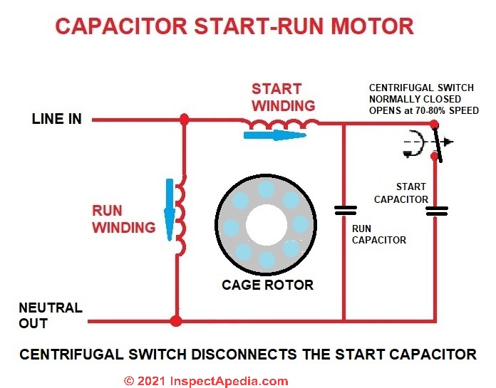
Basic wiring for motor control - Technical data guide | EEP Wiring diagrams show the connections to the controller. Wiring diagrams, sometimes called " main " or " construction " diagrams, show the actual connection points for the wires to the components and terminals of the controller. Basic wiring for motor control - Technical data. They show the relative location of the components. Electric Motor Wiring Diagram 220 to 110 Sample Name: electric motor wiring diagram 220 to 110 - Electric Fan Wiring Diagram With Capacitor Save Capacitor Start Electric Motor Wiring Diagram Fresh For Best Single. File Type: JPG. Source: wheathill.co. Size: 1.27 MB. Dimension: 3229 x 2480.
Motor Connection Diagrams (OLD LECTURE) - YouTube Please use the updated lecture at:
Electric motor diagram with labels
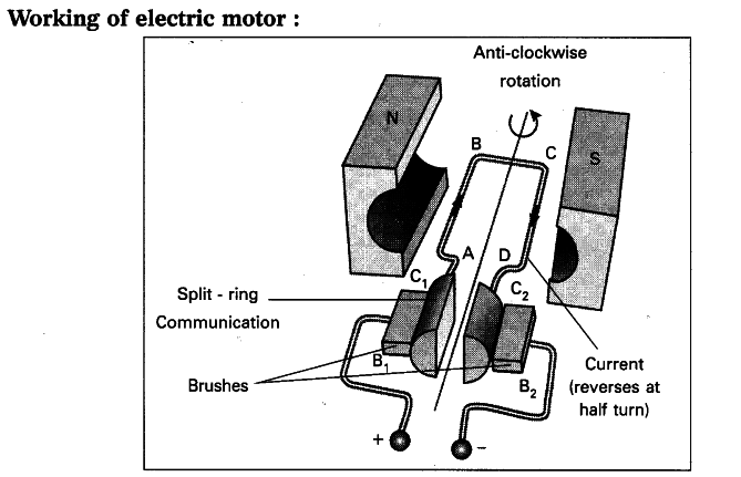
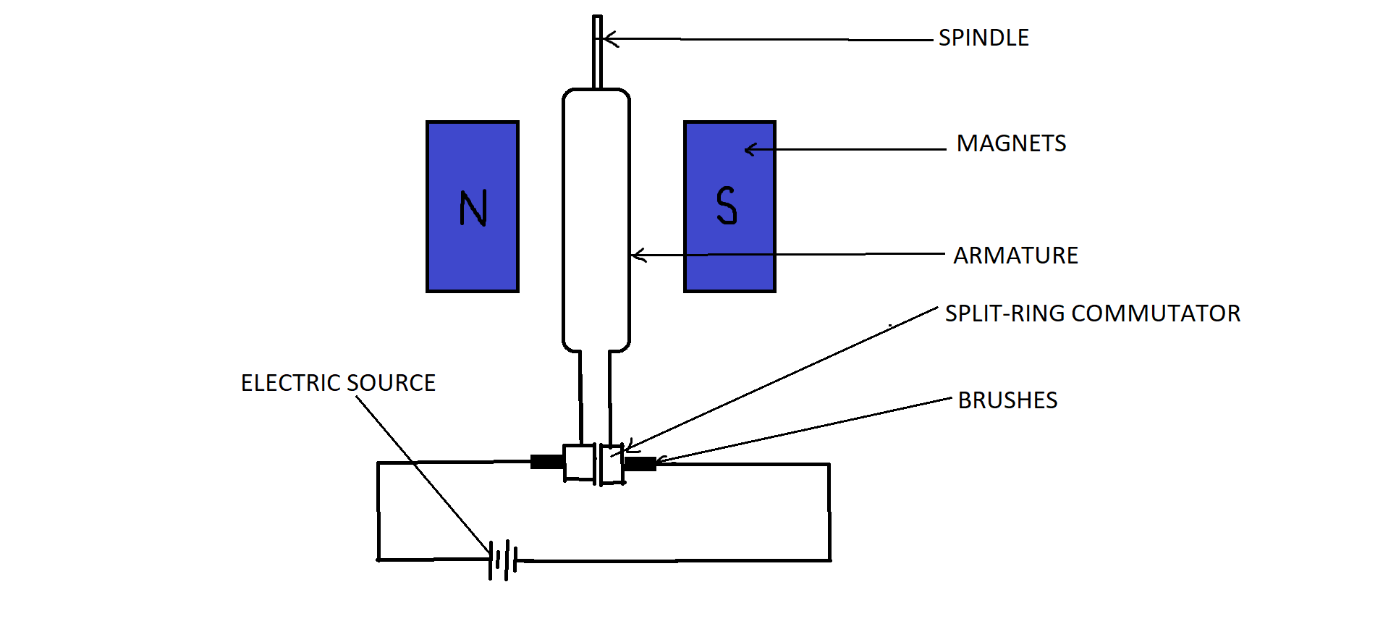
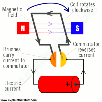
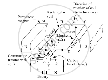
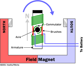
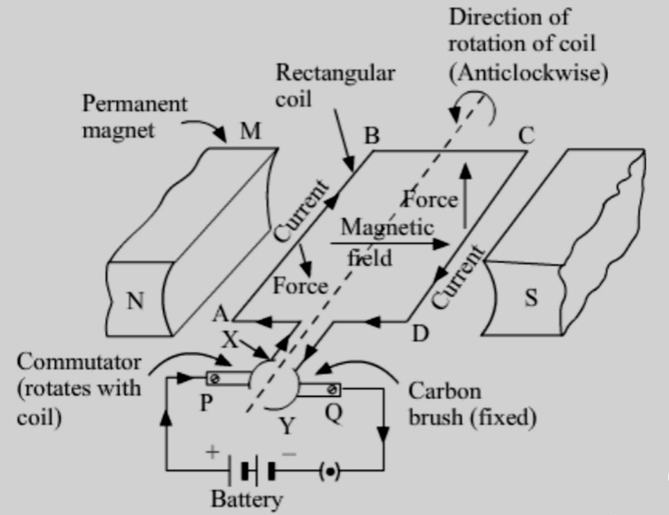
Electric Motor - Parts of Motor, Working of Electric Motor & Uses - BYJUS A simple motor has the following parts: A power supply - mostly DC for a simple motor. Field Magnet - could be a permanent magnet or an electromagnet. An Armature or rotor. Commutator. Brushes. Axle. Power Source: A simple motor usually has a DC power source. It supplies power to the motor armature or field coils. What is an Electric Motor? with the Help of a Labelled Diagram ... An electric motor is a device that converts electrical energy into mechanical energy. Diagram: Electric motor Working of an electric motor: An electric motor works on the principle of magnetic effect of electric current. In an electric motor, a rectangular coil ABCD in placed between two magnets in poles N and S. The picture shows a basic diagram of an electric motor. At top left a ... The picture shows a basic diagram of an electric motor. At top left a piece of magnet labeled N and at top right a piece labeled S. Between these a square coil of wire X sits attached to a metal rod, which runs between the 2 pieces of magnet. 2 semicircular pieces Z of metal surround the rod at its opposite end from the pieces of magnet.
Electric motor diagram with labels. Electrical Symbols, Electrical Diagram Symbols - ConceptDraw Electrical rotating machines, such as motors and generators, are vital assets for any power plant or large industrial company. An electric motor is an electrical machine that converts electrical energy into mechanical energy. The reverse of this would be the conversion of mechanical energy into electrical energy and is done by an electric generator. In normal motoring mode, most ... Single-line Electrical Diagrams | Electric Power Measurement and ... The following schematic diagram represents a segment of an industrial power distribution system containing generators, power transformers, busses (sets of conductors used to connect multiple loads and/or sources in parallel with each other), instrument transformers and meters, circuit breakers, motors, and motor-starting switches: Schematic ... Electric Motor - Principle, Working, Diagram - Explained step by step (a) An electric motor converts mechanical energy into electrical energy. View Answer NCERT Question 11 - Draw a labelled diagram of an electric motor. Explain its principle and working. What is the function of a split ring in an electric motor? View Answer NCERT Question 12 - Name some devices in which electric motors are used. View Answer Electric Motor Symbols - Electrical Symbols Electric motor Generic symbol + Info : Two-speed motor: Electric motor with terminals : AC electric motor Generic symbol + Info: DC electric motor + Info : DC electric motor: Linear motor + Info : Stepper motor + Info: It can do the functions of motor or generator : Permanent magnet DC motor + Info: AC single-phase series motor : DC series motor: Single-phase induction motor with access to winding + Info
Types of electric vehicles with labeled battery and motor outline diagram Types of electric vehicles with labeled battery and motor outline diagram. Illustration about comparison, auto, chassis, outline, isolated, technology, fossil, diagram - 217894989 ... Types of electric vehicles with labeled battery and motor outline diagram. Educational scheme with hybrid, plug-in and electricity car power supply vector ... How to Read an Industrial Pump Motor Wiring Diagram Each motor has several wires in it which are labeled with letters and numbers. For "Line", take the wires the diagram instructs, wrap them together, and connect them to the incoming voltage. For "INSUL", take the wires, wrap them together, and twist them into an insulated cap. Once this is done, the motor is ready to be turned on. General Electric Motor Wiring Diagram - Database Since a rule of thumb, you'll want to have wiring that is very long to extend 3 inches outside of the electrical box. 4. Hide gaps in drywall with oversized plates. Any time you're installing power switches, it's fairly easy to reduce a hole in the drywall that is actually big. Electric Motor Diagrams A Repulsion Electric Motor is by definition a single phase motor which has a stator winding arranged for connection to the source of power and a rotor winding connected to a commutator. Brushes and commutators are short-circuited and are placed so that the magnetic axis of the rotor winding is inclined to the magnetic axis of the stator winding.
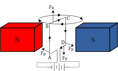
Electrical Diagrams and Schematics - Inst Tools Types of Electrical Diagrams or Schematics. There are three ways to show electrical circuits. They are wiring, schematic, and pictorial diagrams. The two most commonly used are the wiring diagram and the schematic diagram. The uses of these two types of diagrams are compared in Table 1. The pictorial diagram is usually not found in engineering ... What is an Electric Motor? Diagram & Working - ElectricalWorkbook Electric motors are broadly categorized as DC motors and AC motors depending on the type of energy source used. Electric motors produce linear or rotary force (torque). Fig. 4 shows the classification of motors. We can classify the electric motors on the basis of the following parameters: Power source type (AC or DC). Internal construction. How To Read An Electric Motor Nameplate Horsepower Output (kW). Usually labeled as HP or kW, this is the measure of the motors ability to deliver the torque required for the load at a rated speed. hp = 0.746 x kW; conversely, kW =1.34 x hp. Time Rating or duty (DUTY). This designation specifies the length of time that the motor can safely carry its nameplate rating. Question 11 Draw a labelled diagram of an electric motor. Explain its ... Principle: It works on the principle of the magnetic effect of current. A current-carrying coil rotates in a magnetic field. Working: When a current is allowed to flow through the coil MNST by closing the switch, the coil starts rotating anti-clockwise. This happens because a downward force acts on length MN and at the same time, an upward force acts on length ST.
PDF Electrical Symbols and Line Diagrams - University of Florida 14 One Load Per Line Two loads must not be connected in series on one line of a line diagram. If the two loads are connected in series, then the voltage between L1 and L2 must divide across both loads when S1 is closed. The result is that neither device receives the entire 120 V necessary for proper operation.
Electric Motor Nameplate Details Explained | Electric Motor ... The nameplate shown in Figure 1 indicates this motor has an efficiency of 79%. The NEMA full-load efficiency basically lists as a percentage the amount of electrical energy supplied to the electric motor that is converted into kinetic energy. The remaining power is a loss that is converted mostly into heat.
diagram of electric motor diy energy washing motor generator machine wind power generate drive rewire machines alternative smart turbine electric motors solar build homemade. Electric Motors And Controls Training bin95.com. motor electric training controls diagram motors wiring physical parts its [View 25+] Draw The Schematic Diagram Of An Electric Motor And Label It
Draw a labelled diagram of an electric motor. Explain its ... - Sarthaks Principle of Electric Motor A current-carrying conductor, when placed in a magnetic field, experiences a force. If the direction of the field and that of the current are mutually perpendicular then force acting on the conductor will be perpendicular to both and will be given by Fleming's left-hand rule.
Electric Motors Symbols - AC/DC, Single Phase / Three Phase Motors This symbol represents a single phase AC synchronous motor. Synchronous motors initially starts as an induction motor but later achieves a synchronous speed which only depends on the input supply frequency. DC Compound Excitation Motor. Such type of DC motor has both the series field winding and shunt (or parallel) field winding.
19 Essential Information You Can Find On Motor Nameplate | EEP Nameplate-defined parameters for the motor such as power factor, efficiency, torque and current are at rated voltage and frequency. When the motor is used at other voltages than the voltage indicated on the nameplate, its performance will be affected. Voltage on motor nameplate. 2. Frequency.
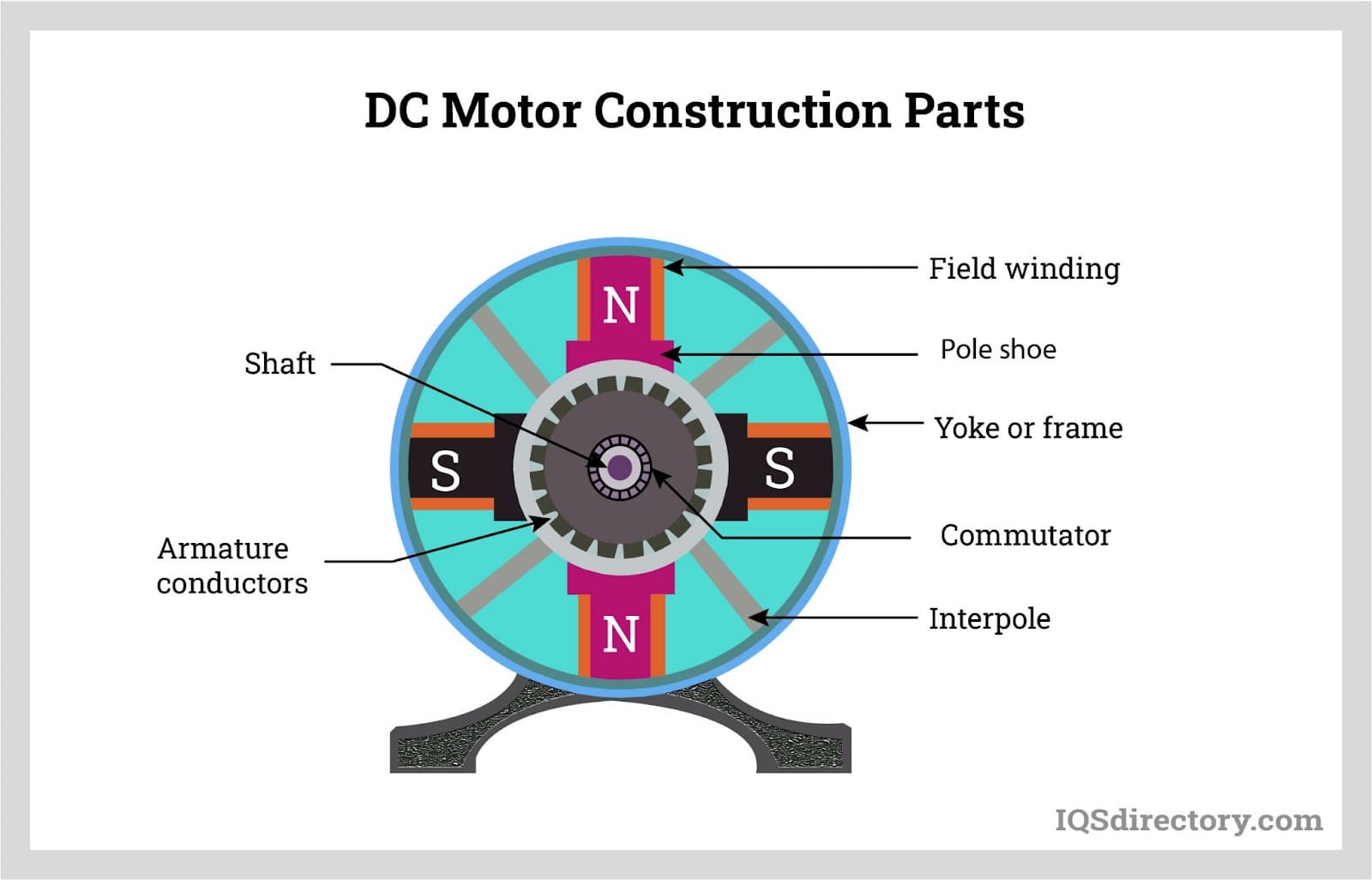
Draw a labelled diagram of a d.c. motor. - toppr.com The carbon brushes are connected to a D.C. source. Working of the Electric motor: When the coil is powered, a magnetic field is generated around the armature. The left side of the armature is pushed away from the left magnet and drawn towards the right, causing rotation. When the coil turns through 90 degrees, the brushes lose contact with the ...
Car engine diagram hi-res stock photography and images - Alamy RF T1TN8A - Generic Car Diagram. A ghosting or cross section of a car showing the engine, drive train and suspension. RF 2B0W66Y - Gasoline cars and electric cars comparison infographic with icons, cars refueling and charging at the station and car parts diagram, automotive techno. RF 2FK1CAT - Mechanic working on car in his shop,Portrait ...
Electric Car Diagram | Car Construction Car Anatomy and Repair, Electric car, Engine, How a car Works, Construction. The active reference to source is obligatory if you use materials of a site Car Anatomy 1054 shares
Motor Connection Diagrams - Electric Motor Warehouse Single Phase Terminal Markings Identified By Color: (NEMA Standards) 1-Blue 5-Black P1-No color assigned. 2-White 6-No color assigned P2-Brown. 3-Orange 7-No color assigned. 4-Yellow 8-Red. Three Phase Connections: Part Winding Start: 6 Leads NEMA Nomenclature: WYE or Delta Connected.
PDF Understanding Electric Motor Nameplates - Michigan State University In Table 1, there is a column labeled shaft diameter. Figure 2 This is a bottom view of an electric motor showing the mounting bracket and ... VOLTS Electric motors must be matched to the voltage of the circuit. Some motors are only single voltage. If that is the case, then only one voltage will be shown on the nameplate. ...
The picture shows a basic diagram of an electric motor. At top left a ... The picture shows a basic diagram of an electric motor. At top left a piece of magnet labeled N and at top right a piece labeled S. Between these a square coil of wire X sits attached to a metal rod, which runs between the 2 pieces of magnet. 2 semicircular pieces Z of metal surround the rod at its opposite end from the pieces of magnet.
What is an Electric Motor? with the Help of a Labelled Diagram ... An electric motor is a device that converts electrical energy into mechanical energy. Diagram: Electric motor Working of an electric motor: An electric motor works on the principle of magnetic effect of electric current. In an electric motor, a rectangular coil ABCD in placed between two magnets in poles N and S.
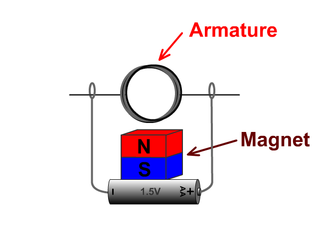
Electric Motor - Parts of Motor, Working of Electric Motor & Uses - BYJUS A simple motor has the following parts: A power supply - mostly DC for a simple motor. Field Magnet - could be a permanent magnet or an electromagnet. An Armature or rotor. Commutator. Brushes. Axle. Power Source: A simple motor usually has a DC power source. It supplies power to the motor armature or field coils.






![Expert Verified] draw a labelled diagram of an electric motor ...](https://hi-static.z-dn.net/files/dab/56da13db27ea5b6a3128c7861117c25a.jpg)







Post a Comment for "43 electric motor diagram with labels"